HIGH-PERFORMANCE OPTICAL MEASUREMENT EQUIPMENT AND SYSTEM SOLUTION

APPLICATION

(File B-2) TO MEASURE NFP OF MMF (multi-mode optical fiber) USING 850nm LD LIGHT SOURCE

OUTLINE

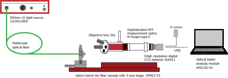
Measurement method of near field pattern of MMF (multi-mode optical fiber) by NFP measurement is shown below. As the light source, 850nm LD light source is used. As NFP measurement system, Synos' sophisticated optical beam NFP measurement optics/M-Scope type S, high resolution digital CCD detector/ISA011, objective lens/M-Plan Apo 20x, are selected and arranged.

MEASUREMENT SYSTEM

MEASUREMENT SYSTEM BLOCK DIAGRAM
SYSTEM COMPONENT
  • Optical beam NFP measurement system
    • Light source
      • High stability FC connector output LD light source (850nm) / LSL002/850
    • Optics
      • Sophisticated optical beam NFP measurement optics / M-Scope type S
  • Objective lens
    • M-Plan Apo 20×
  • Detector
    • High resolution digital CCD detector / ISA011
  • Image processing and analysis
    • Optical beam analysis module AP013
  • Optics bench
    • Optics bench for fiber measurement with 3-axis stage / OP002-F3

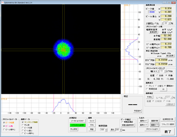
MEASUREMENT RESULT 1(Beam shape, Beam width)

Result of MMF NFP measurement, using 850nm LD light source, is shown as left-hand image.

  • Beam width: Vertical 52.342um / Horizontal 52.940um(1/e2 width)
  • Measurement condition
    • Total magnification:objective lens 20×
    • Pixel resolution:0.2325um
    • Dark calibration:ON
    • Integration time:8times

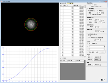
MEASUREMENT RESULT 2(ENCIRCLED FLUX ANALYSIS)

In addition, from the acqcuired MMF NFP image, encircled flux analysis is done as shown in left-hand image.

  • EF graph:shown in left-hand image
  • EF analysis condition
    • Center:gravity of area
    • Setting of analysis area criteria:30um
    • Setting of analysis radius coefficient:1.15
    • Setting of sampling pitch:0.1um
    • Background calibration:done (coefficient 1.2)

POINTS OF SYSTEM SELECTION

  • Optics selection
    • As measurement optics, Synos' optical beam NFP measurement optics/M-Scope type S is selected. As objective lens, 20x is selected. As the result of this optics selection, real observation view is approx. 320um x 240um, and pixel resolution is approx. 0.23um.
  • Detector selection
    • As imaging detector, Synos' high resolution digital CCD detector/ISA011 is selected, because of having high resolution and sensitivity in 850nm region, good gamma characteristic, good durability against input light, etc.
  • EF analysis function
    • Synos' NFP analysis method is image processing and analysis method by using magnifying optical system and image detector.The two-dimensional light intensity distribution of the laser beam is captured as an image and image analysis is performed. Therefore, in addition to normal emission beam profile analysis, it can also handle power distribution analysis such as EF analysis. EF analysis function is standardly installed in our optical beam analysis software Optometrics BA Standard.

RELATED PRODUCT CATALOG DOWNLOAD